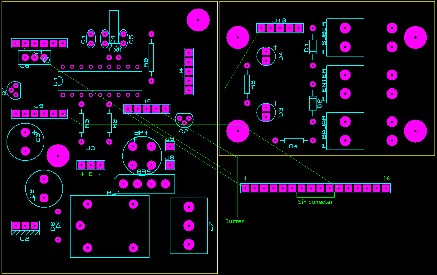
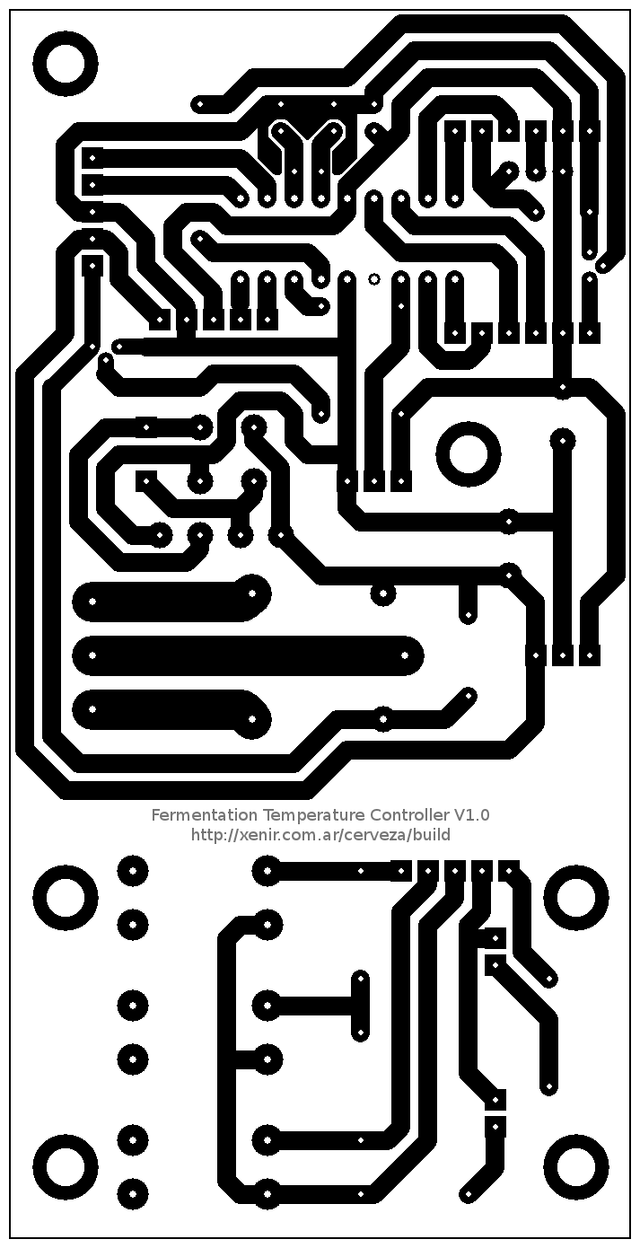
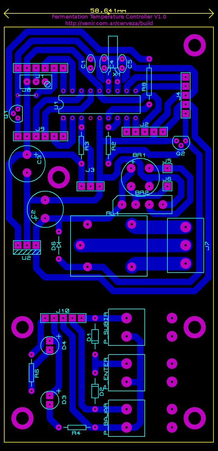
PCB:
The main purpose of this program (and circuit) is get a robust, reliable,
simple and cheap fermentation controller unit.
This was achieved using a well know microchip PIC, cheap and easy to get
in almost any country.
The operation mode it's pretty clear; you set (using buttons and display)
each temperature according to each fermentation stage and how many days the
system must remain using that temperature, turn on and the circuit will take
care of your beer temp. It supports up to 3 fermentation stages.
Of course this circuit did not chill the beer by itself, needs to be used in
conjunction with fridge, fermentation chamber or also electric heaters
at cold places.
The circuit was tested on many differents situations, and we can say that
still is performing flawless since two years after his installation.

Some routines (LCD and 1Wire) are just adaptions from originals found on
'Microcontrolador PIC16F84 - Desarrollo de proyectos' written by
Enrique Palacios, Fernando Ramiro and Lucas López
Delays (retardos) routines were calculated using PicLoops 2.2

Quick PIC pinout:
        1. LCD Data Bit 1 of 4
        2. LCD Data Bit 2 of 4
        3. DS18B20 Temp Sensor 1Wire data
        4. MCLR (must be set to HI if MCLR is enabled)
        5. GND (PIC power)
        6. LCD Backlight control (through BC548)
        7. Cooler/Heater output, to toggle relay or similar
        8. Buzzer output
        9. Clock for 7Segs display output (using CD4094)
        10. 'Bajar' button input
        11. 'Subir' button input
        12. Xtal input 32.768 kHz
        13. Xtal input 32.768 kHz
        14. +5v (PIC power)
        15. LCD Data Bit 3 of 4
        16. LCD Data Bit 4 of 4
        17. LCD R/S Pin / Data for 7Segs display output (using CD4094)
        18. LCD Enable Pin
          C1      0.1 uF
          C4,C5   0.22 pF
          J1      Trimmer 5 KOhms
          X1      Xtal 32.768 KHz
          J8      Bridge
          R3,R8   4.7 KOhms
          J1      Output LCD 2x16 HD44780
          J2      Output Buzzer / 3x7 segments
          J3      Output DS18B20
          J4      Output buttons.
          J5,J6   9V AC
          J9      Output LCD 2x16 HD44780
          J10     Buttons input.
          Q1,Q2   BC548
          R2      150 Ohms
          BR1,BR2 Rectifier, only one is needed.
          C2, C3  470 uF x 16v
          D6      1N4007
          AL1     Relay coil 12V (SRD-S-112D)
          J7      Terminal block
          U1      PIC 16F648
          U2      LM7805
          D3,D4   Leds
          R6,R4   1 KOhms
          D1,D2   1N4148
          P_???   Buttons